Multitask Noisy Speech Enhancement System
www.denoise.net
Example
Restorer
- Speech band equalizer
- Dynamics processing
- Noise gate
- Signal level limiter
- Clipping restoration
- Noise reduction
- Noise whitening
- Blind deconvolution
- Spectrum analyser
- Time stretching
- Spectral expander
- Fourier corrector
- Neural network corrector
- Decorrelation
- Joint approximation
- Homomorphic approximation
- Reverberation
Recorder
Browser
- Synchronisation
- Normalisation
Contact info
Clipping restoration
The task of the clipping restoration module is to detect parts of the recorded signal which are distorted due to clipping and to restore the signal. While the signal level limiter module prevents clipping that occurs during the processing, the clipping restoration module processes signal that is already clipped.
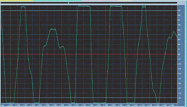
An example of clipped speech recording (zoomed):

The algorithm identifies part of a recording as clipped if at least three consecutive sound samples have identical or similar value. The values of clipped samples are estimated using second order interpolation on the basis of three non-clipped sound samples that precede the clipped section. Both forward and backward interpolations are performed. The restored values of the samples are calculated from the interpolation results and optionally smoothed using the linear prediction method.
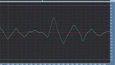
The restored portion of clipped signal:

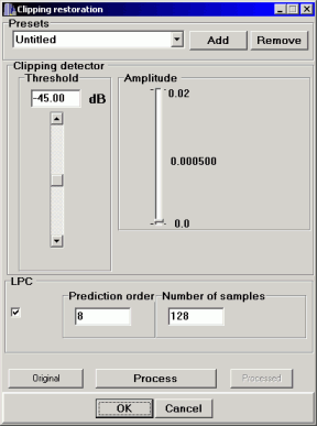
The following parameters may be set by the user:
- threshold level (from -90 to 0 dB) - parts of the signal below this level are not used in clipping detection;
- amplitude - maximum difference between two adjacent samples values in clipping detection (from 0 to 0.02, assuming that amplitude is normalized to the range from -1 to 1);
- predictor turned on or off;
- prediction order (how many samples are used to estimate new sample value)
- number of non-clipped sound samples used by the predictor in calculation of the prediction coefficients

Clipping in the sound file is often caused by signal overdrive in the analogue system (for example, due to too high signal level or impedance mismatch). In this case, clipping may occur at different levels (if clipping is caused by digital signal processing procedures, it usually occurs at the maximum amplitude). The values of distorted samples are usually similar, but not identical. The clipping restoration module is useful in this case.
The parts of the signal below the threshold level are not analysed by the clipping detector. If user sets the threshold to the minimum value of -90 dB, all samples are analysed, which greatly increases time needed to analyse the whole sound file. It is recommended to perform analysis of the sound file before it is processed, using a sound editor, in order to find the optimal value of the detection threshold.
If the signal is digitally clipped, the distorted samples usually have the same value. In the case of analogue clipping, the distorted samples will generally have similar, but not identical values. The amplitude parameter defines the maximum difference between the values of consecutive samples that are still considered as clipped. The user may choose amplitude from 0 to 0.02. If the amplitude is too low, many distorted parts of the signal will not be detected. Satisfactory results are usually obtained for amplitude set to 0.01. If the non-distorted parts of the signal will be incorrectly classified as clipped, they will not be distorted by the restoration module, they will only be slightly smoothed.
The optional linear prediction algorithm (LPC) smoothes the signal after clipping restoration. The number of samples used in prediction should be greater than the prediction order, usually values of 512 or 1024 samples are correct. If the signal is highly distorted due to clipping, these parameters should be as small as possible, so that distorted samples do not have significant influence on the values of restored samples.